Detailed explanation of wiring method for reactor junction box
Detailed explanation of wiring method for reactor junction box
Keyword: reactor junction box, junction box for reaction kettle, load cell box
I: Definition and function of reactor junction box
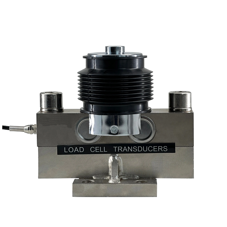
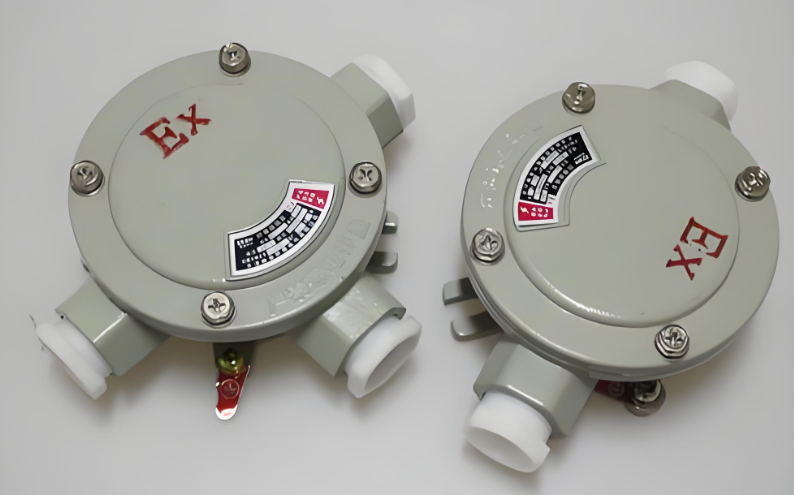
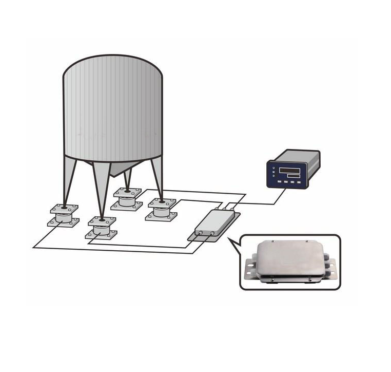
The reactor junction box is an interface device that connects weighing sensors and weighing instruments, and plays a role in transmitting weighing signals. Widely used in various weighing fields, such as finished product weighing in industrial production, pricing scales in commercial places, and cargo scales.
II: Introduction to the interface of the reactor junction box
The reactor junction box of a weighing display generally consists of a weighing sensor interface, a power interface, an instrument interface, and a calibration interface. Among them, the weighing sensor interface is the interface that connects the sensor, usually with three wires, namely the red, black, and green wires; The power interface is an interface that connects to a power source, usually with two wires, the red and black wires; The instrument interface is the interface that connects instrument devices, usually consisting of four wires, namely red, black, white, and green wires; The calibration interface is the interface used to connect debugging equipment and calibrate the measurement accuracy of the reactor.
III: Wiring method for reactor junction box
1: Before wiring, it is necessary to confirm the voltage of the equipment used and the type of weighing sensor, ensuring that the matching 4-wire sensor reactor junction box matches the sensor to avoid damaging the equipment.
2: Insert the red, black, and green wires of the cable into the corresponding positions of the reactor junction box according to the markings on the weighing display. Three wires are respectively connected to the "+", "-", and "E" interfaces of the junction box for reaction kettle, where the "+" interface corresponds to the red wire and is connected to the positive pole of the power supply; The "-" interface corresponds to a black wire, which is connected to the negative pole of the power supply; The "E" interface corresponds to the green wire, which is connected to the grounding wire of the sensor.
3: If an instrument needs to be connected, insert the instrument interface. The red and black wires on the instrument interface are connected to the positive and negative terminals of the power supply, the white wire is connected to the "+" interface of the sensor, and the green wire is connected to the "-" interface of the sensor.
If calibration is required, the corresponding debugging equipment can be inserted according to the identification of the calibration interface.
IV: Precautions
1:The weighing display junction box for reaction kettle should be disconnected from the power supply before wiring to avoid the risk of electric shock.
2:When inserting the wire head, pay attention to the direction and ensure that the plug is aligned with the socket.
When connecting the instrument, the power supply of the instrument should be turned off first before wiring.
4:When conducting calibration and debugging, carefully read the debugging equipment manual and follow the correct operating methods.
After the wiring is completed, a test should be conducted to confirm the measurement accuracy of the weighing equipment.
Through the introduction in this article, everyone can understand the definition and function of the reactor load cell box, as well as the functions and wiring methods of each interface. I hope this article can help everyone better use the reactor load cell box and improve work efficiency.
Analysis of the Working Principle of Tank Scale Weighing System
How to connect the wiring of the Weighing Junction Box
Related Article